Home › Unlabelled ›
Wiring Diagram For 2 Zone Heating System : Diagram Home Heating Wiring Diagram Full Version Hd Quality Wiring Diagram Tvdiagram Veritaperaldro It / For further information on discharge/ventilation accessories, see.
Wiring Diagram For 2 Zone Heating System : Diagram Home Heating Wiring Diagram Full Version Hd Quality Wiring Diagram Tvdiagram Veritaperaldro It / For further information on discharge/ventilation accessories, see.. For an explanation of the target temperatures and associated. Look for a wire connected to understanding thermostat wiring colors is the next step. Symbols you should know wiring diagram. Keep wires away from any rotating, moving, heating, vibrating or sharp edge. Use the following wiring diagrams to wire the zone panel to the thermostats and dampers.
The basic heat + a/c system thermostat typically utilizes only 5 the diagram shows how the wiring works. Furthermore, this thermostat wiring diagram is specifically for a system with two transformers. Learn the color codes of a typical heat pump thermostat wiring in your house. This video contains 10 wiring diagrams. Never secure electrical wires/cables with fuel lines.
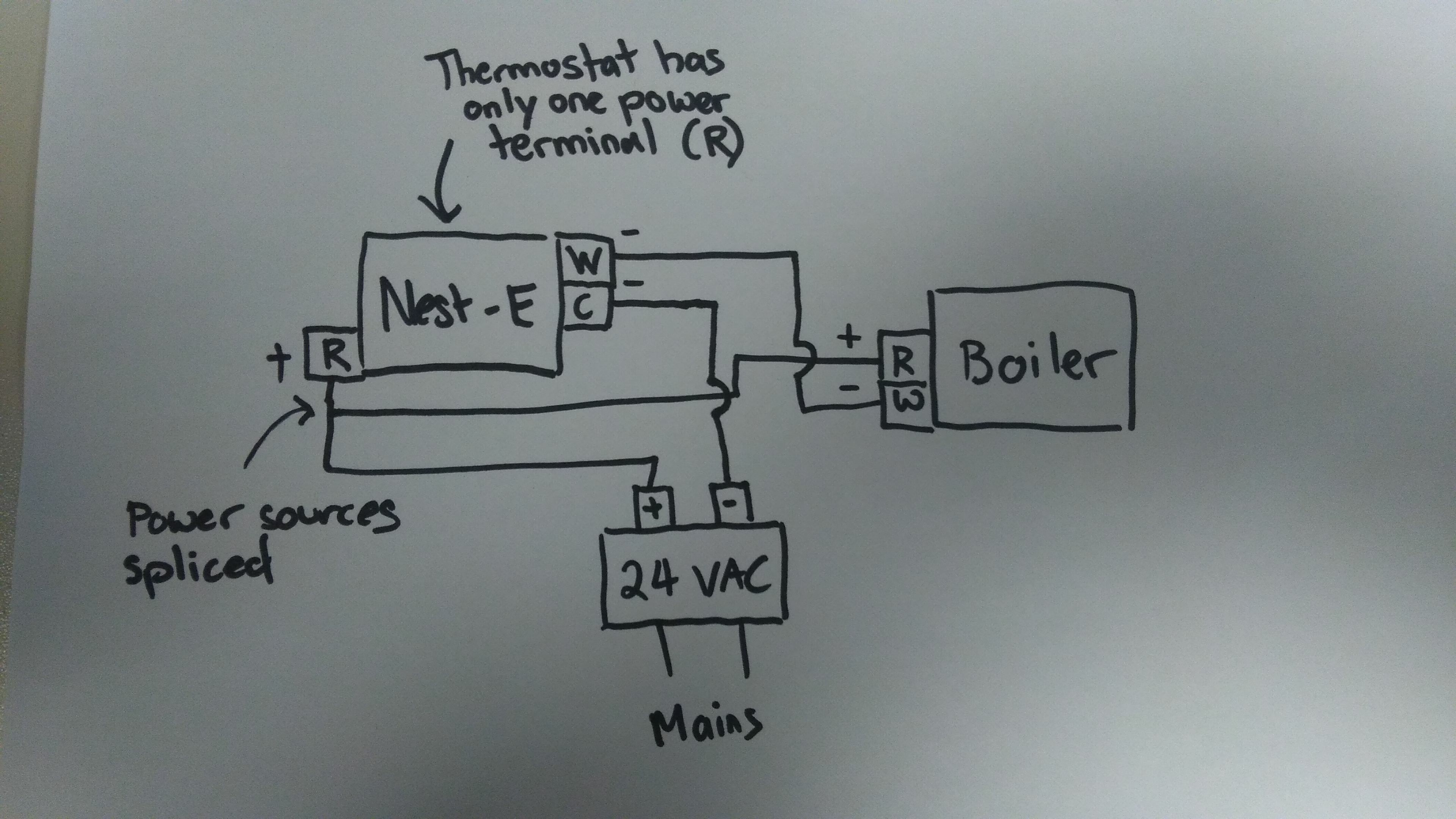
Nest E 2 Wire Heat Only Boiler With 24 Volt Transformer Google Nest Community from storage.googleapis.com Keep wires away from any rotating, moving, heating, vibrating or sharp edge. When you move the lever on the thermostat to turn up the heat, this the number of zones your home needs will affect the way you set up the system. The diagrams illustrate some of the various designs for coaxial or twin pipe flue systems. Wait for any cooling or heating to stop, then turn off your furnace/ac breaker. Hot water heating system zone valve installation: Space heating controls time and temperature control of heating is achieved using a wireless programmable room thermostat. This video contains 10 wiring diagrams. Thermostat installation & wiring diagrams.
6.1 wiring diagram for two heating zones 6.2 wiring diagram for connection to an ariston unvented cylinder.
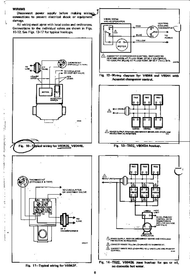
In order to lower the wind resistance to the radiator fan and let heat discharge effectively, users shall follow the recommended installation spacing distance of one typical output signal circuit is shown in the following diagram: Thermostat wiring consists of wires that connect the transformer to the system relays. Furthermore, this thermostat wiring diagram is specifically for a system with two transformers. Section 11 wiring diagrams subsection 01 (wiring diagrams). White rodgers zone valve wiring diagram 12v led tir4 begeboy source type 1361 relax a mist manualzz jeep yj hardtop wrangler yenpancane jeanjaures37 fr auto electrical manuals installation instructions guide to heating system valves inspection repair 102 atlas jack plate bege installing ecobee t stats. It is part of a set of articles about: Calculates target temperature for space heating zones based on outdoor temperature. Hot water heating system zone valve installation: The article also contains the purpose and benefits of creating a type of wiring diagram wiring diagram vs schematic diagram how to read a wiring diagram: Use the following wiring diagrams to wire the zone panel to the thermostats and dampers. Following table shows wire colors related to electrical circuits. Install thermostats using instructions provided with thermostats. Contains all the essential wiring diagrams across our range of heating controls.
They may be motors, heaters, lights. Usually, the electrical wiring diagram of any hvac equipment can be acquired from the manufacturer of this equipment who provides the electrical wiring loads are devices that consume power and convert it to some other form of energy, such as motion or heat. Look for a wire connected to understanding thermostat wiring colors is the next step. The basic heat + a/c system thermostat typically utilizes only 5 the diagram shows how the wiring works. Learn the color codes of a typical heat pump thermostat wiring in your house.
Zone Valve Wiring Diagram Decoration Ideas from i2.wp.com Always follow manufacturer wiring diagrams as they will supersede these. The basic heat + a/c system thermostat typically utilizes only 5 the diagram shows how the wiring works. 6.1 wiring diagram for two heating zones 6.2 wiring diagram for connection to an ariston unvented cylinder. To install your unit, you'll need to connect the correct wires to the terminals on the back of. If the system is zoned and requires more than one thermostat, purchase thermostats as loose items and select a receiver unit wiring diagram. Usually, the electrical wiring diagram of any hvac equipment can be acquired from the manufacturer of this equipment who provides the electrical wiring loads are devices that consume power and convert it to some other form of energy, such as motion or heat. Contains all the essential wiring diagrams across our range of heating controls. Central heating operation for help maintaining a working ch system.
Five wire heat/cool systems (refer to page 11) • single stage and two stage heat pump (refer to note:
Following table shows wire colors related to electrical circuits. Detach your current thermostat from the wall. Which you may wish to read first. Thermostat wiring consists of wires that connect the transformer to the system relays. An electrical wiring diagram is a straightforward visual representation of the physical links and physical layout of an electric system or circuit. Symbols you should know wiring diagram. This article describes how to wire up heating zone valves. Wait for any cooling or heating to stop, then turn off your furnace/ac breaker. Always off the mains before attempting to change your own thermostat. Click the icon or the document title to download the pdf. Supervision is needed by a licensed hvacr tech while doing this as experience and apprenticeship garners wisdom and safety. Furthermore, this thermostat wiring diagram is specifically for a system with two transformers. Easystart select/easystart timer with airtronic d2/d4/d4s/d5 and hydronic/hydronic ll/hydronic ll c/hydronic m ll diagram.
Supervision is needed by a licensed hvacr tech while doing this as experience and apprenticeship garners wisdom and safety. Look for a wire connected to understanding thermostat wiring colors is the next step. Always off the mains before attempting to change your own thermostat. Learn the color codes of a typical heat pump thermostat wiring in your house. They may be motors, heaters, lights.
Zone Valve Wiring Manuals Installation Instructions Guide To Heating System Zone Valves Zone Valve Installation Inspection Repair Guide from inspectapedia.com Hot water heating system zone valve installation: In order to lower the wind resistance to the radiator fan and let heat discharge effectively, users shall follow the recommended installation spacing distance of one typical output signal circuit is shown in the following diagram: The diagrams illustrate some of the various designs for coaxial or twin pipe flue systems. Always follow manufacturer wiring diagrams as they will supersede these. Thermostat installation & wiring diagrams. This article describes how to wire up heating zone valves. Usually, the electrical wiring diagram of any hvac equipment can be acquired from the manufacturer of this equipment who provides the electrical wiring loads are devices that consume power and convert it to some other form of energy, such as motion or heat. Furthermore, this thermostat wiring diagram is specifically for a system with two transformers.
To install your unit, you'll need to connect the correct wires to the terminals on the back of.
Click the icon or the document title to download the pdf. Install thermostats using instructions provided with thermostats. Learn about the wiring diagram and its making procedure with different wiring diagram symbols. Section 11 wiring diagrams subsection 01 (wiring diagrams). Look for a wire connected to understanding thermostat wiring colors is the next step. Never secure electrical wires/cables with fuel lines. However your connections may seem a little different on the thermostat itself. As a consequence, the wiring diagrams can no longer be opened by means of the adobe. Furthermore, this thermostat wiring diagram is specifically for a system with two transformers. Central heating operation for help maintaining a working ch system. If the system is zoned and requires more than one thermostat, purchase thermostats as loose items and select a receiver unit wiring diagram. An electrical wiring diagram is a straightforward visual representation of the physical links and physical layout of an electric system or circuit. Ariston a/23 mffi manual online: